CNC Basics
Under Construction
Introduction
This paper is intended to acquaint a newcomer to the world of CNCs. As a woodworker, the world of CNCs has its own unique techniques, vocabulary and process flow. This article, though not exhaustive, hopefully will introduce the reader to some of the basic aspects of the CNC system.
Where Do I Start
First off, we need to ask the simple question, what is a CNC machine? The CNC machine is a machine used for producing products through an automation system. This system includes a software stack that is used to design the product (such as a CAD program) and generate the codes for telling the CNC machine how to move (such as a CAM program). The CNC machine itself will have a controller that interprets those generated codes and produces the product. Some software programs such as Vcarve by Vectric are integrated so that you can design and create the CNC machine code in one interface.
Mechanically, the CNC machine uses a series of step motors (a motor that can be controlled in a precise manner) that controls a cut, usually by a spindle motor such as a router that contains a cutting bit. This system uses the geometrical XYZ coordinate system for defining the movement of arms in a psuedo 3 dimensional manner. This system is the basis for other manufacturing systems such as laser engraving/cutting, 3D printing, 3D scanning. The XYZ movement is controlled by a set of code commands called G-Code.
CNC, at its heart, is more a process framework that has been an evolving system since its original development in the 1950s. The US Air Force established a CNC standard which was needed in being able to manage large scale projects between manufacturers. Over the decades, the CNC process framework and application in its evolutionary refinement has expanded covering new uses. One such new use case is the replacement for the need to stock parts in a warehouse, producing parts only at the time it is needed in a manufacturing or retail setting.
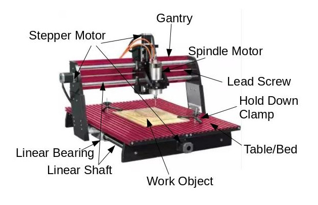
Below is a picture of a wood cutting CNC machine that will acquaint you with some of the basic parts. Pictured is a Next Wave Automation “CNC Shark”. Not pictured is the machine controller.
The Sky is the Limit?
Can the CNC system be used for all applications? Technically the answer is “yes” and “no”. Though the CNC system is a sophisticated solution that has a wide range of application, there are limitations to its capabilities. Here is a list of things to consider in using a CNC system as a work solution:
- For simple applications or one time use, it might be quicker to do it manually. Most of the work is in the pre-production stage. Effort and time is needed to create the design, test and refine the G-Code instruction set that guides the CNC machine to perform its work. It is always wise to prototype production before producing your final product.
- Production time might be too long. The more complicated a design is, the more time it will take to produce the product especially if that design requires cutter bit changes. Also to consider, if there are multiple copies of the product to be produced, it may take too much time and producing the product manually might be quicker.
- When extreme accuracy is required, even if a simple application, it may make sense to have the CNC create your product.
- True 3D products may not be possible. Depending on the type of CNC machine you have, doing complicated work such as true 3D work may not physically be possible since the machine was not designed to function in a true 3D manner. For example, if the spindle motor can only vertically and a horizontal cut is required, the machine physically is unable to make the required horizontal cut. Most machines are capable for “2.5D” projects. This means that a psuedo 3D image can be attained in a relief form on a single surface.
- Bed size of the CNC machine dictates how large your project can be. For oversized projects, the width is fixed. It could be possible to cut extended widths by breaking up the project into two parts and re-position the project between parts. This can be very difficult.
Overview of the Process
Consider this workflow:
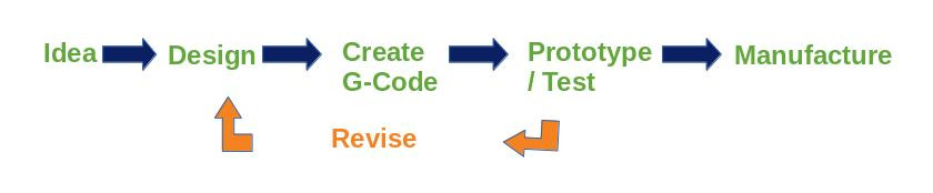
First, you have to have an idea. What is it you wish to produce? For simple projects and depending on the design software you are using, you can start with a JPEG picture of the object you wish to produce. There are also forums and stores on the internet where you can purchase and/or download a file ready to use.
It is necessary to create what is called a vector graphic formatted picture. This is ultimately what is used by the software to figure out how to define the XYZ paths for the cutter bit to follow. Decisions are made here as to what cutter will be used and how deep the cutter will travel. Sometimes multiple passes are needed with cutter (aka tool) changes needed. Expertise here comes as you develop your skill in working with the software in conjunction with the CNC machine.
Most CNC software will have a feature that will allow you to visualize the path of the cuts as well as the direction the spindle motor will travel before dropping the cutter onto the surface of your object. Better software even has a feature that animates how the spindle motor will travel to better visualize the operation in production. This step is a point for review to see roughly what your object will look like in terms of how the CNC machine sees it. This may require going back to your design and tweaking the design in a way that will accommodate how the object will be cut when you go to production.
When the design is complete, G-Code is created and saved as a file to either a USB thumb drive or a micro SD chip depending on the manufacturer of the CNC machine. The file is then connected to the CNC machine and executed there.
It is important to prototype. Using cheap or scrap material is important to try out the G-Code that the software had produced. Logically, you could potentially waste expensive or irreplaceable material if you go straight to final production. After reviewing your prototype, you may need to go back to design and perform any needed tweaks.
Lastly, is the final production step. Being confident that your prototype produced the desired result, you are ready for producing the final product.
Some considerations to consider in design:
- Can I perform this in one pass with one cutting bit or will it take multiple passes with a “tool change”?
- Can I create multiple products out of one sheet of material in one pass?
- Where will my XY data (0, 0) coordinate be established (e.g. in the center, left front corner, etc.)? Where will my Z data coordinate fall (e.g. material surface or the CNC bed)?
- How deep should the cuts be?
- If the cut is intended to go completely through the material, it may need to have ???? left behind for manual cutoff. You don’t want the piece to take flight when the CNC makes the final cut.
- How fast should the cutter go? Roughly, the deeper and broader the cut is, the slower the speed. The harder the material also factors in.
Conclusion
The CNC system has transformed manufacturing on a large scale. It’s evolution has provided a quality solution that can be used on a small and hobby scale. While there is a learning curve, it can be a rewarding hobby or provide a low cost solution for a small business.